


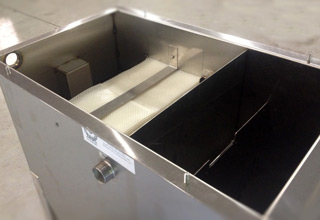
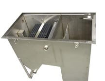
Above Ground Oil Water Separators (ECOS)
Oil water separators are used to separate oils and solids from a variety of wastewater discharges. Above ground oil water separators will remove large quantities of free or mechanically emulsified oils from a waste stream. Our units can process oily wastewater at rates between 2 to 70 gallons per minute.
 Request a Quote
System Design
Design Features
- Stainless Steel construction
- Compact size
- No chemicals, absorbent, or filter cartridges
- 99.99% removal of free oil >20 microns
- No moving parts
- No power consumption
- Meets EPA Method 413.2 and European Standard EN 858-1
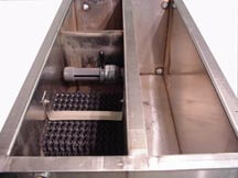
- High surface area – 132 ft² per 1ft³
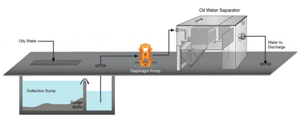
Process Illustration
Oil Water Separator Available Models (Flow rates based on oil at 0.9 specific gravity)
AGS Series (up to 20 gpm)
| Model Number | Description | Flow Rate GPM | Dimensions | Capacity Gallons |
AGS-1SS |
Flat Bottom |
2 - 5 | 16"W X 28"H X 52"L | 60 |
AGS-1SS-30V |
W / Sump |
2 - 5 | 16"W X48"H X 52"L | 75 |
AGS-1SS-HP |
W / Sludge Hopper |
2 - 5 | 16"W X 48"H X 52"L | 75 |
AGS-1SS-30V-HP |
W / Sump & Sludge Hopper |
2 - 5 | 16"W X 48"H X 52"L | 82 |
AGS-2SS |
Flat Bottom |
3 - 10 | 28"W X 28"H X 52"L | 120 |
AGS-2SS-60V |
W / Sump |
3 - 10 | 28"W X 48"H X 52"L | 174 |
AGS-2SS-HP |
W / Sludge Hopper |
3 - 10 | 28"W X 48"H X 52"L | 134 |
AGS-2SS-60V-HP |
W / Sump & Sludge Hopper |
3 - 10 | 28"W X 48"H X 52"L | 188 |
AGS-3SS |
Flat Bottom |
5 - 15 | 40"W X 28"H X 52"L | 180 |
AGS-3SS-90V |
W / Sump |
5 - 15 | 40"W X 28"H X 52"L | 270 |
AGS-3SS-HP |
W/ Sludge Hopper |
5 - 15 | 40"W X 48"H X 52"L | 200 |
AGS-3SS-90V-HP |
W / Sump & Sludge Hopper |
5 - 15 | 40"W X 48"H X 52"L | 360 |
AGM Series (20–60gpm)
| Model Number | Description | Flow Rate GPM | Dimensions | Capacity Gallons |
AGM-1SS |
Flat Bottom |
3 - 10 | 16"W X 28"H X 64"L | 75 |
AGM-1SS-30V |
W / Sump |
3 - 10 | 16"W X 48"H X 64"L | 105 |
AGM-1SS-HP |
W / Sludge Hopper |
3 - 10 | 16"W X 48"H X 64"L | 89 |
AGM-1SS-30V-HP |
W / Sump & Sludge Hopper |
3 - 10 | 16"W X 48"H X 64"L | 119 |
AGM-2SS |
Flat Bottom |
6 - 20 | 28"W X 28"H X 64"L | 150 |
AGM-2SS-60V |
W / Sump |
6 - 20 | 28"W X 48"H X 64"L | 195 |
AGM-2SS-HP |
W/ Sludge Hopper |
6 - 20 | 28"W X 48"H X 64"L | 178 |
AGM-2SS-60V-HP |
W / Sump & Sludge Hopper |
6 - 20 | 28"W X 48"H X 64"L | 223 |
AGM-3SS |
Flat Bottom |
9 - 30 | 40"W X 28"H X 64"L | 225 |
AGM-3SS-90V |
W / Sump |
9 - 30 | 40"W X 48"H X 64"L | 279 |
AGM-3SS-HP |
W / Sludge Hopper |
9 - 30 | 40"W X 48"H X 64"L | 267 |
AGM-3SS-90V-HP |
W / Sump & Sludge Hopper |
9 - 30 | 40"W X 48"H X 64"L | 321 |
AGM-1SS-1H |
Flat Bottom |
6 - 20 | 16"W X 40"H X 64"L | 86 |
AGM-1SS-36V-1H |
W / Sump |
6 - 20 | 16"W X 60"H X 64"L | 142 |
AGM-1SS-HP-1H |
W / Sludge Hopper |
6 - 20 | 16"W X 60"H X 64"L | 96 |
AGM-1SS-36V-HP-1H |
W / Sump & Sludge Hopper |
6 - 20 | 16"W X 60"H X 64"L | 152 |
AGM-2SS-1H |
Flat Bottom |
12 - 40 | 28"W X 40"H X 64"L | 172 |
AGM-2SS-73V-1H |
W / Sump |
12 - 40 | 28"W X 60"H X 64"L | 217 |
AGM-2SS-HP-1H |
W / Sludge Hopper |
12 - 40 | 28"W X 48"H X 64"L | 194 |
AGM-2SS-73V-HP-1H |
W / Sump & Sludge Hopper |
12 - 40 | 24"W X 58"H X 64"L | 239 |
AGM-3SS1H |
Flat Bottom |
18 - 60 | 40"W X 40"H X 64"L | 258 |
AGM-3SS-118V-1H |
W / Sump |
18 - 60 | 40"W X 60"H X 64"L | 325 |
AGM-3SS-HP-1H |
W / Sludge Hopper |
18 - 60 | 40"W X 60"H X 64"L | 290 |
AGM-3SS-118V-HP-1H |
W / Sump & Sludge Hopper |
18 - 60 | 40"W X 60"H X 64"L | 357 |
AG Series (35–2000gpm)
| Model Number | Description | Flow Rate GPM | Dimensions | Capacity Gallons |
AG-1SS |
Flat Bottom |
9 - 30 | 16"W X 40"H X 88"L | 157 |
AG-1SS-38V |
W / Sump |
9 - 30 | 16"W X 60"H X 88"L | 172 |
AG-1SS-HP |
W / Sludge Hopper |
9 - 30 | 16"W X 60"H X 88"L | 185 |
AG-1SS-38V-HP |
W / Sump & Sludge Hopper |
9 - 30 | 16"W X 60"H X 88"L | 200 |
AG-2SS |
Flat Bottom |
18 - 60 | 28"W X 40"H X 88"L | 314 |
AG-2SS-75V |
W / Sump |
18 - 60 | 28"W X 60"H X 88"L | 340 |
AG-2SS-HP |
W / Sludge Hopper |
18 - 60 | 28"W X 60"H X 88"L | 343 |
AG-2SS-75V-HP |
W / Sump & Sludge Hopper |
18 - 60 | 28"W X 60"H X 88"L | 369 |
AG-3SS |
Flat Bottom |
27 - 90 | 40"W X 40"H X 88"L | 471 |
AG-3SS-113V |
W / Sump |
27 - 90 | 40"W X 60"H X 88"L | 540 |
AG-3SS-HP |
W / Sludge Hopper |
27 - 90 | 40"W X 60"H X 88"L | 550 |
AG-3SS-113V-HP |
W / Sump & Sludge Hopper |
27 - 90 | 40"W X 60"H X 88"L | 619 |
AG-4SS |
Flat Bottom |
36 - 120 | 52"W X 40"H X 88"L | 628 |
AG-4SS-150V |
W / Sump |
36 - 120 | 52"W X 60"H X 88"L | 680 |
AG-4SS-HP |
W / Sludge Hopper |
36 - 120 | 52"W X 60"H X 88"L | 750 |
AG-4SS-150V-HP |
W / Sump & Sludge Hopper |
36 - 120 | 52"W X 60"H X 88"L | 802 |
AG-4SS-1H |
Flat Bottom |
60 - 170 | 52"W X 52"H X 88"L | 840 |
AG-4SS-240V-1H |
W / Sump |
60 - 170 | 52"W X 72"H X 88"L | 900 |
W / Sludge Hopper |
60 - 170 | 52"W X 72"H X 88"L | 960 | |
AG-4SS-240V-HP-1H |
W / Sump & Sludge Hopper |
60 - 170 | 64"W X 72"H X 88"L | 1010 |
Oil Water Separator Available Options
Sludge Hopper Option
Oil water separators designed with the sludge hopper option allow for the natural settling of heavy solids. The hopper has a port that can be connected to a sludge transfer pump.
Clean Water Sump Option
Oil water separators designed with the clean water sump allow for a float swith and submersible pump for pumping clean water into a different location.
Sludge Hopper Option
Oil water separators can be built with both sludge hopper and clean water sump to perform multiple tasks in a single unit.
Oil Containment Chamber
Captured oil can be collected for resale or reuse. The optional oil containment compartment has an upper and lower port for pulling oil out of the holding chamber.
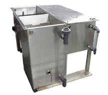
Oil Containment with Sight Glass Option
Oil water separators can be modified with sight glasses to allow for visual inspection of clean water sump and oil containment tank levels.